
MB Series Dosing Pumps
MOTOR-DRIVEN DOSING PUMP
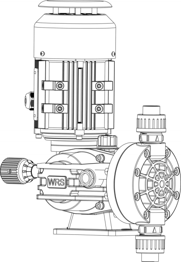
The MB series dosing pump is a positive displacement piston dosing pump with a mechanical drive. It is widely used in industrial and scientific fields such as petrochemical, chemical, food, pharmaceutical, paper, light industry, agriculture, environmental protection in water bodies, etc., and is responsible for measuring and adding various media during the process. Various pump head materials are available to handle different types of liquids. The standard configuration is PVC material; other materials such as 304, 316, and PVDF are also available.
MB series dosing pumps can handle corrosive or non-corrosive liquids without solid particles within the temperature range of -15 °C to 60 °C and viscosity range of 0.3–1000 cps. The nominal flow rate of the pump is from 10 to 1800 L/h, and the corresponding maximum output pressure is from 10 to 1 bar. The pump flow rate is adjusted by rotating the handwheel, and the adjustment can be made from 0 % to 100 % regardless of whether the pump is running or not. The steady-state accuracy is ±1 % within the flow range of 30 % to 100 %. This is a dosing pump with a simple design, low power consumption, accurate measurement, and practicality. Various types of dosing pumps can be equipped with explosion-proof motors or variable frequency motors upon customer request.
Features
- High flow capacity — up to 1800 L/h.
- Non-hermetic design.
- Smooth flow adjustment in both operating and non-operating states.
- Specifically designed for handling aggressive liquids.
- Various material options for different applications.
- Adjustable flow in both operating and non-operating states.
- Robust and reliable — designed for heavy-duty applications.
- Compact modular design.
- Dosing accuracy of ±1 % within 10–100 % of the nominal flow rate.
- Double-ball check valve for easy maintenance.
- Easy replacement of parts.
- Multi-layer diaphragm for extended service life.
GENERAL PUMP SPECIFICATIONS
| Model | MB |
| Type | Mechanical diaphragm with motor drive |
| Flow rate (L/h) | 240–1800 |
| Pressure (bar) | 10–3 |
| Pump head material | Standard: PVC. Optional: PVDF, SS304, SS316 |
| Operation mode | Continuous or intermittent |
| Number of pump heads | 1 |
| Connection type | Adhesive connection / Welded connection |
| Flow adjustment method | Adjustable handwheel |
| Flow adjustment display method | Analog display |
| Remote control | With optional ON/OFF drive |
| Suction lift (m) | 3 |
| Number of valve balls | One |
| Strokes per minute | 48–144 |
| Accuracy | ±1 % at 30–100 % flow rate |
| Weight (kg) | Gross weight: 34 kg. Net weight: 37 kg |
DRIVE SPECIFICATIONS
| Standard motor | IEC STANDARD MOTOR. Power: 0.3 kW. Voltage: 220 V/380 V, 4P 3ph 50 Hz. Protection: IP55 / Class F / TEFC |
| Optional motors (on request) | IEC VFD / EXD / VFD + EXD MOTOR. Voltage: 220 V/380 V, 4P 3ph 50 Hz. Protection: IP55 / Class F / TEFC |
ENVIRONMENTAL SPECIFICATIONS
| Fluid temperature range (°C) | -15 to 60 |
| Fluid viscosity range (cps) | 0.3–1000 |
| Ambient temperature range (°C) | -30 to 80 |
| Outdoor use | Yes, provided it is sheltered from rain and direct sunlight |
DIAPHRAGM DETAILS
| Diameter (mm) | 148–185 |
| Material |
Layer 1: PTFE Layer 2: EPDM rubber Layer 3: 3.0 mm SUS304 Layer 4: Nylon fiber Layer 5: EPDM rubber |
Product Images
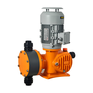
PVC Pump Head
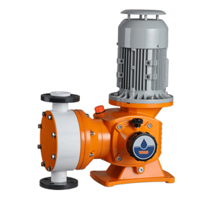
PVDF Pump Head
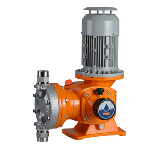
SS304/316 Pump Head
Model Selection
| Model | Strokes per minute (min⁻¹) | Nominal flow rate (L/h) | Nominal pressure (bar) | Nominal power (W) | Connection type | ||
|---|---|---|---|---|---|---|---|
| (PVC) | (PVDF) | (SS316) | |||||
| MB0250 | 48 | 250 | 10 | 0.75 | DN25 Adhesive connection | RC 1″ NPT internal thread | RC 1″ NPT internal thread |
| MB0320 | 48 | 320 | 10 | ||||
| MB0500 | 96 | 500 | 10 | ||||
| MB0680 | 96 | 680 | 7 | ||||
| MB0760 | 144 | 760 | 5 | ||||
| MB1000 | 144 | 1000 | 4 | ||||
| MB1200 | 96 | 1200 | 4 | 1.1 | DN40 Adhesive connection | RC 1 1/2″ NPT internal thread | RC 1 1/2″ NPT internal thread |
| MB1600 | 144 | 1600 | 3 | ||||
| MB1800 | 144 | 1800 | 3 | ||||
Material Selection
| Pump Head Material | Valve Body | Valve Seat | Valve Ball | Diaphragm | O‑Rings | Inlet/Outlet |
|---|---|---|---|---|---|---|
| PVC | PVC | PVC | Ceramic | PTFE | Viton | PVC |
| PVDF | PVDF | PVDF | Ceramic | PTFE | Viton | PVDF |
| SS304 | SS304 | SS304 | SS304 | PTFE | PTFE | SS304 |
| SS316 | SS316 | SS316 | SS316 | PTFE | PTFE | SS316 |
For detailed chemical compatibility tables, please refer to the manufacturer’s documentation.
Dimensions
Product dimensions for MB Series Motor‑Driven Diaphragm Dosing Pump with PVC Pump Head:
| Model | Pump Head Material | Connection | A (mm) | B (mm) | C (mm) | D (mm) | E (mm) |
|---|---|---|---|---|---|---|---|
| MB0240–MB1000 | PVC | DN25 Glue Union | 310 | 180 | 143 | 416 | 525 |
| PVDF | RC 1″ Female NPT | 273 | 180 | 144 | 414 | 525 | |
| SS304/316 | RC 1″ Female NPT | 280 | 180 | 135 | 390 | 525 | |
| MB1200–MB1800 | PVC | DN40 Glue Union | 410 | 220 | 153 | 431 | 560 |
| PVDF | RC 1 1/2″ Female NPT | 342 | 220 | 150 | 437 | 560 | |
| SS304/316 | RC 1 1/2″ Female NPT | 368 | 220 | 139 | 401 | 560 |
Installation Guidelines
- Site Selection: Choose a level, stable surface protected from direct sunlight and precipitation. Ensure adequate ventilation for motor cooling.
- Foundation: For models MB1200–MB1800, secure the pump to a solid foundation using mounting bolts (M12 recommended). Smaller models (MB0240–MB1000) may be surface-mounted with vibration isolation pads.
-
Piping:
- Use compatible materials per fluid type (PVC, PVDF, or stainless steel).
- Install isolation valves on inlet/outlet lines.
- Ensure no stress or tension on pump connections.
- For suction lines > 3 m, use a foot valve and prime the pump before startup.
-
Electrical:
- Connect to a dedicated circuit with overcurrent protection (see motor specs).
- Ground the motor per IEC 60364 standards.
- For VFD/EXD motors, follow manufacturer wiring diagrams.
-
Initial Startup:
- Fill pump head with fluid to prime diaphragm.
- Open inlet/outlet valves slowly.
- Run at 0 % stroke for 5 minutes to purge air.
- Gradually increase flow rate while monitoring pressure.
Maintenance Schedule
| Component | Check Interval | Action |
|---|---|---|
| Diaphragm | Every 6 months | Inspect for cracks/wear. Replace if PTFE layer is compromised. |
| Valve Balls/Seats | Every 3 months | Clean with compatible solvent. Replace if pitted or scored. |
| O‑Rings | Annually | Replace if hardened or deformed. |
| Motor Bearings | Every 2 years | Lubricate per IEC 60034-14. Replace if noisy. |
| Electrical Connections | Semi‑annually | Tighten terminals. Check insulation resistance. |
Troubleshooting
| Symptom | Possible Cause | Solution |
|---|---|---|
| Low Flow Rate | Air in pump head | Prime pump. Bleed air via vent valve. |
| Worn valve balls/seats | Replace valves. | |
| Excessive Noise | Loose mounting | Tighten foundation bolts. |
| Bearing failure | Replace motor bearings. | |
| Leakage at Head | Damaged diaphragm | Replace diaphragm assembly. |
| Motor Overheating | Overloaded pump | Reduce flow rate. Check fluid viscosity. |
For detailed service procedures, refer to the MB Series Service Manual (Document #SM‑MB‑2023).
Contact Support:
Email: marketing@poliplast.ru
Phone: +7 (8112) 66-39-06